Designed for the LH Electronics display system
The ECN works as the engine-side sensor node for the CDM CAN Display Module, creating a cleaner modular setup between the engine bay and helm.
Product updates
Development updates from LH Electronics, including the Engine CAN Node and CDM CAN Display Module ecosystem.
The latest update shares progress on a custom in-house designed PCB that brings traditional engine signals into the LH Electronics smart display system.
Latest update
The LH Electronics Engine CAN Node is a dedicated sensor interface module designed to modernise traditional engine wiring and bring older engine signals into the LH Electronics smart display system.
Mounted close to the engine, the ECN reads key engine information such as tach/RPM, battery condition, oil, temperature, fuel, trim and alarm switch inputs. These signals are conditioned, protected and converted into clean digital CAN data for the CDM CAN Display Module.
Instead of routing every individual sender and alarm wire all the way to the helm, the ECN keeps the engine-side wiring local and sends the display module a robust digital data feed.
This gives the system its own dedicated hardware platform, developed around the real signal handling needs of older marine engines.
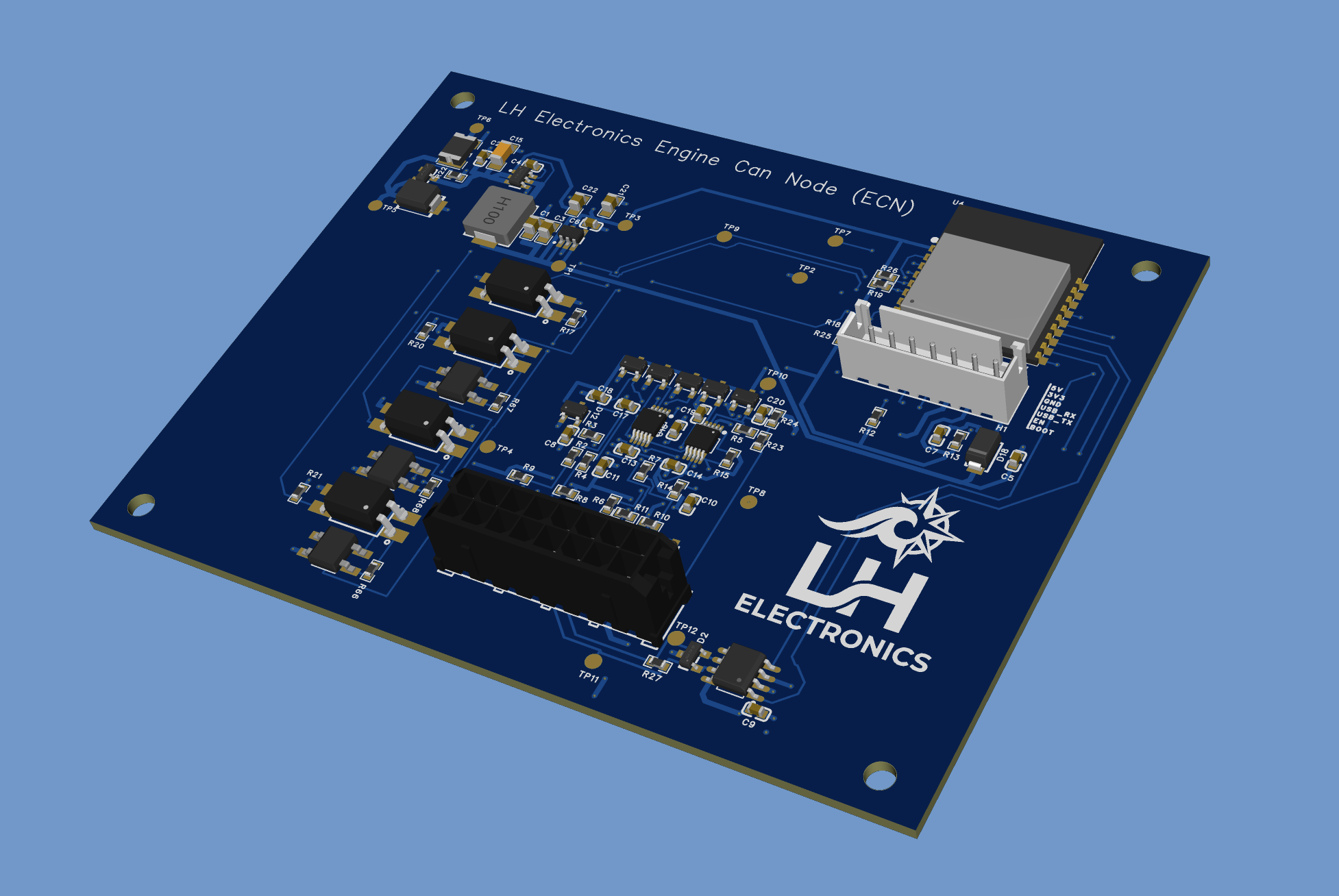
Key areas
The ECN works as the engine-side sensor node for the CDM CAN Display Module, creating a cleaner modular setup between the engine bay and helm.
Inputs are designed with protection and signal conditioning in mind so sensitive electronics are not exposed directly to raw sender and switch wiring.
Oil, temperature, fuel and trim sender inputs are read through dedicated measurement circuitry, allowing firmware calibration for different sender types.
Alarm switch states are handled separately from analogue sender channels so measured values and direct alarm states can be shown together.
The tach input is conditioned before processing, giving the firmware a clean signal for configurable RPM measurement.
The ECN supports battery condition monitoring so the display can report system voltage and low-voltage conditions.
Spare analogue and digital input capacity is included for future features, custom installations or additional monitoring options.
Engine-side information is converted into clean CAN data for a robust local data feed to the display module.
Protection and Conditioning
The ECN has been designed as a proper engine interface. Input stages include protection, filtering and conditioning methods suited to noisy engine wiring.
Analogue sender inputs are conditioned before measurement, helping to reduce noise and protect the measurement circuitry. Switch and alarm inputs are handled through protected input stages, keeping harsh external signals away from the processor side of the board.
System architecture
The ECN communicates with the CDM CAN Display Module using CAN, giving the system a robust local data link and allowing future LH Electronics modules to be added to the same ecosystem.
This architecture reduces dashboard wiring, improves signal handling and creates a cleaner upgrade path for modern smart dashboards on supported older boats.
Compliance note
The ECN is built around certified processor-module hardware with published RF compliance documentation for major markets. This helps reduce wireless compliance risk when integrated according to the manufacturer’s guidance. Final product compliance remains dependent on the completed product, enclosure, installation and target market requirements.